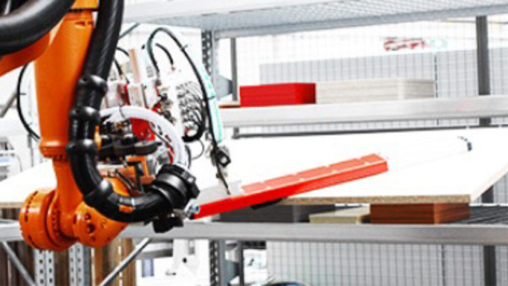
The key advantages of such sorting cells are:
- Component sorting turns a chaotic flow of parts from parts production into a controlled material flow for downstream processes
- Workpieces can be sorted out according to different criteria such as carcase decor, parts group, material group, target workstation in the subsequent process or completeness of the carcase parts, etc. Material flow can thus be further optimized
- Multiple function consisting of parts buffering + decoupling of the edging system from the downstream process + component sorting + completeness of components on removal for downstream processing
- Increased productivity (unmanned parts sorting, changed sequence in parts production) and material utilization (CAN parts in cutting plan optimization)
When selecting a sorting cell, it is essential to know and take into account the customer’s individual requirements. This is because they inevitably lead to different system solutions:
- Basic manufacturing philosophy in component production –> strictly order-related parts production or series production in a parts warehouse (as a clear parts reference or as a master part) or a mixture of both variants
- Hall height, other constructional conditions
- Design of the edging machine as a single machine or two/four single-sided edging machines in interlinking
- Ø Cycle output and max. Power peaks pieces of components per minute/hour/day
- Manual or automated loading/unloading/stacking or a mixture of the two
- Minimum and maximum component dimensions, part thicknesses
- Storage capacity dependent on the customer’s requirements for part volumes, process organization and actual process reliability (scare buffer)
- Sorted parts in individual part access or intermediate storage according to part reference with part reassignment
- Capital expenditure budget
Accordingly, a wide variety of solutions can be considered:
- KBS rack with pick by light: Simple, manual yet system-supported sorting cell in combination with a pick-by-light system; workpieces are assigned to a storage compartment by scanning; the operator confirms the storage of the component at the touch of a button and thus establishes a clear reference in terms of data technology. The pick-by-light display provides the employee with visual support during retrieval.
- Vertical lift system with trays – e.g. KARDEX-Shuttle XP: Carcass parts/fronts are manually placed on a tray and married to the tray by scanning the component/component label; for higher cycle rates, the sorting cell may consist of two or more devices. During storage and retrieval, the order picker can also be supported by a laser pointer. In one expansion stage, a combination with robots would be feasible, but restrictions due to part dimensions and stack heights would have to be taken into account.
- Round cells with robots: e.g. the SORTBOT R-300 robot sorting cell from HOMAG; here, 16 shelves are arranged in a circle around a centrally positioned robot, thus offering a maximum storage capacity. 700 components. The workpieces are fixed upright between brushes so that individual parts can be accessed at any time.

One and the same robot stores and retrieves individual parts – at the expense of cycle and cell performance. A similar system is offered by IMA Schelling. The workpieces are sucked in/handled with a lean vacuum system and buffered horizontally in the racks. This requires reference-related part stacks (same length+width+thickness+decor+groove) and reallocation and labeling during component picking.
- Sorting cell with robots on traversing axis and sorting wall: The Fives sorting concept differs in that the infeed, storage side is decoupled from the outfeed, retrieval side by means of a sorting wall in the form of a push-through rack. This leads to clear material flows that do not overlap or negatively influence each other.
The advantages of this principle are No process-related waiting times or alternating process faults, the overall system becomes simpler with significantly higher system availability. The storage and retrieval robots move on linear axes in order to increase the reach of the individual robots. Depending on the length of the parts, up to three parts per robot cycle are handled on the infeed side; the buffer capacity of this sorting cell is approx. 3000 parts. On the outsourcing side, the components are traded exclusively as individual parts. Consequently, several robots are required to handle the volume of parts. The final dividing sequence for the subsequent process is generated in the outfeed section with system support.
- Sorting robot on traversing axis with direct picking into trolleys: In this variant, the concept described above has been further developed so that the components arriving from an edging line are picked up by picking robots and picked directly into the waiting transport trolleys on the corresponding storage compartments.

This variant requires an exact allocation of the cutting lots to the picking lots with strict trolley allocation. In this solution, CAN parts are buffered in a plug-in rack above the picking trolleys and picked to the correct picking lot = trolley with a time delay. With this concept, fewer degrees of freedom in the production organization are offset by lower investment costs. Providers of such concepts are Fives Cinetic and Rotte.
- Sorting cell for series and commissioned parts: This expansion variant could be of interest to all furniture manufacturers whose production philosophy is a mixture of ‘series and A parts on pallets in stock and B and C parts produced to order’.

The serial parts are placed under a destacking gantry, picked layer by layer and the parts are separated; the quantity required for picking goes into the picking line, the remaining layers as CAN parts into the sorting buffer. The components produced for specific orders are buffered randomly in exactly the same sorting buffer and removed from storage in the correct parts sequence as required. With the help of a material flow control system, the two material flows are brought together to create the correct stacking sequence and assembly sequence for the assembly lines.
As shown, there are a number of specific solutions and technical concepts – but there is no single solution that is always right and valid for everyone! It is therefore always necessary to consider and weigh up the individual requirements/needs/range of parts/conditions/framework conditions. Consequently, the evaluation of which solution approach may be suitable for the respective application is very important. This evaluation is based on detailed data analyses, supported in part by simulation tools. This allows processes to be mapped and validated very realistically.


